
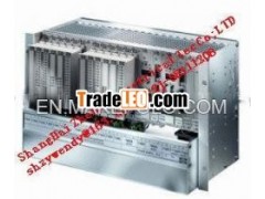


B 5230: Assemly Kit / H51q-M: System
System H51q-M in K 1412B system subrack, 5 HU, 19 inches withsingle channel central module,
power supply 24/5 V, power supply monitoring module, I/O busconnection, communication
modules (optional), coprocessor modules (optional) and threefans
Figure 1: Front view
1 Parts of the B 5230 assembly kit /
H51q-M system
• 1 x K 1412B central rack, 5 units high, 19 inches, with cabletray with three fan modules
K 9212, hinged receptacle for the label and backplane Z 1001.
• additional modules on the rear
• 3 x Z 6011 decoupling and fusing to feed the power supplymodules
• 1 x Z 6018 fan run monitoring and fuse monitoring
• 2 x Z 6013 decoupling and fusing of the supply voltage for the WDsignal
• 2 x F 7546 bus termination modules
includes the modules:
• 2 x F 7126 power supply modules 24 V / 5 V, 10 A (PS1, PS2)
• 1 x F 7131 power supply monitoring
• 1 x F 8651X central module (CU1)
modules for option (separate order)
• 3 x F 8621A coprocessor module (CM11 - CM13)
• 5 x communication modules (CM11 - CM15)
• 1 x F 7126 power supply module 24 V / 5 V, 10 A (PS3)
Assembly kits to be used for the I/O level:
• B 9302 I/O subrack 4 units high, 19 inches
• B 9361 additional power supply, 5 VDC, 5 units high, 19inches
F7126 F7126 F7126 F7131 F8651X F8621A F8621A F8621A
H51q-M B5230
NG1/PS1 NG2/PS2 NG3/PS3 ZB1/CU1
1 2 3 4 5 6 7 8 9 10 11 12 13 14 15 16 17 18 19 20 21
Option Option
HIMA
F8627X
1 2
1
2
1 2
1
2
1 2
1
1 2 2
HIMA
F8621A
HIMA
F8621A
HIMA
F8621A
HIMA
F8627X
HIMA
F8651X
HIMA
F7126
HIMA
F7131
HIMA
F7126
HIMA
F7126
10baseT HSR
TX COL
ERR
FB
RUNRED
FB
10baseT HSR
TX COL
ERR
FB
RUNRED
FB
PS1 PS2 PS3 CU1 CM11 CM12 CM13 CM14 CM15 K 1412B
B 5230 / H51q-M (0605)
2/10
The max. current must be 18 A (all I/O modules and the modules inthe central rack), if
3 x F 7126 are used to keep the system in operation even one powersupply module F 7126
has failed.
Values of the current requirement ( 5 V DC) refer to the datasheets.
2 Modules
2.1 Central module F 8651X
The central module of the PES H51q-M contains the essentialfunctions demonstrated in the
block diagram of the central module:
Figure 2: Block diagram of the central module F 8651X
– Microprocessor
– Flash-EPROMs of the program memory for the operating system andthe user program
usable for min. 100,000 writing cycles
– Data memory in sRAM
– Dual Port RAM for fast memory access to the second central module(not used in the
H51q-M system)
– 2 interfaces RS 485 with galvanic isolation. Transmission rate:max. 57600 bps
– 4digit diagnostic display and 2 LEDs for information out of thesystem, I/O level and user
program
– Power supply monitoring
– I/O bus logic for the connection to the input/output modules
– Hardware clock, battery buffered
– Watchdog
– Battery backup of the sRAMs via batteries on the central modulewith monitoring
Note Operating system/resource type in ELOP II
The assembly kit is usable since operating system BS41q/51qV7.0-8.
Resource type in ELOP II: H51qe-M.
Watchdog
B 5230 / H51q-M (0605)
3/10
2.2 Coprocessor module F 8621A
Right of each installed
Hima Safety Systems B 5230: H51q
